Early Anita Desktop Calculators
ANITA Mk 8

ANITA Mk 8
The ANITA Mk 8, made by the Bell Punch Co. of Uxbridge, England, was launched in October 1961. Together with the concurrently introduced ANITA Mk VII, for the continental European market, it was the world's first electronic desktop calculator. It was sold mainly in the rest of the world outside of continental Europe, and was announced at the Business Efficiency Exhibition, in London, in October 1961[1], but orders for it were not taken by the British distributor, Sumlock Comptometer Ltd., until January 1st 1962.
This model and the Mk VII were the only electronic desktop calculators in the world for over two years, and many thousands were sold. Like the Mk VII it has a full keyboard and uses cold-cathode tube technology.
Development of the ANITA calculators was started in 1956 under Norbert Kitz (a.k.a. Norman Kitz), who had worked on the pilot version of the ACE (Automatic Computing Engine) computer project in the mid 1940s.
The name ANITA, stands variously for "A New Inspiration To Arithmetic" and "A New Inspiration To Accounting". This became the family name for all the Bell Punch electronic models.
Display - 12-digits Numerical indicator tubes (similar to "Nixie" tubes).
Electronics -
- One Dekatron decade counter tube of type Hivac GS10D.
- About 180 cold-cathode tubes of types Mullard Z700U and Hivac XC31.
- Selenium rectifiers.
- 10 vacuum tubes (thermionic valves) of type ECC81.
- 1 transistor of type Ferranti ZT42.
A pulse rate of 4 KHz is used by the electronics. This may appear to be very slow today, but it was very fast compared with the mechanical calculators available then, and is acceptable for calculations with the standard four functions.
Size - 376 x 450 x 255 mm (14.75" x 17.75" x 10"), 13.9 Kg (30.5 lbs).
Cost in 1964 was £355 Sterling [about $1000].
Manufactured by the Bell Punch Company, Uxbridge, England.
The Mk8 was available in several slight variations - Mk8A, Mk8AA, and Mk8AB.
The photographs here show the Mk8A machine with model/serial number C/8/009067/A.
One visible difference is that the Mk8AA models do not have the Non-shift control switch at top left.
The manufacturer had previously specialised in full-keyboard, "Comptometer"-type, mechanical calculators. The early Anitas used similar full-keyboards and worked in a similar way to a Comptometer since just pressing one of the number keys of the main keyboard immediately added that number to the total being displayed - it was not necessary to press any = key. Addition is very fast since all the fingers can be used to press keys in different columns simultaneously.
An article in the journal New Scientist in 1975 stated "The Anita machine was built under licence by numerous foreign firms, including Olympia in the United States and Sharp in Japan".
If you can confirm
that other companies did build these machines please get in touch with me.
Click here for a review of the ANITA Mk 8 made in late 1961 when it was launched.
If you have information about the development of Anita calculators, or know of somebody who worked there, please get in touch with me .

Advertisment for the Anita Mk 8, June 1964.


The keyboard of the ANITA resembles that of the mechanical Comptometer, with the keys 1 to 9 in each decade.
For addition, the "+" key at lower left is engaged and numbers are entered on the main keyboard, directly in the appopriate decade column. Addition is instantaneous and the sum is indicated immediately as each key is pressed. The full keyboard and instantaneous display of the result means that for addition this type of machine can be much faster than a 10-key calculator, as explained on the Operating a Comptometer page.
Subtraction works similarly after the "-" key is engaged.
For multiplication or division, the appropriate key at bottom left is engaged, then the first number is entered on the main keyboard. The second number is entered in the column of keys on the right with the decimal point entered in the correct position using the Mutiplier Decimal Point key.
The 'U' shape to the left of the keyboard is a slide-in holder for a card with decimal conversions, especially for converting the old British Sterling currency to its decimal equivalent.
This full keyboard was to also used in the Mk 9 model (which also allowed chain multiplication) and the Mk 10 model (with some capability of calculations involving the old British £sd currency), but for subsequent models a standard 10-key keyboard was used.

The rear legs of the ANITA are extendable so that the whole machine can be tilted forward to place the keyboard at a more ergonomic angle.
Most of the case of the ANITA is plastic, with the sides and the bottom being one large moulding.

With the display cover removed the 12 "Nixie"-type numerical display tubes are revealed. Each is mounted on the edge of a register/display board and is lacquered red to give better visibility to the
displayed number.
At the bottom of the display tubes and between them are neon lamps which are used to produce the decimal point in the display. This was a common feature of Anita calculators, and some others, into the early
1970s.

Looking down from the rear with the keyboard hinged forwards, showing that the neon tubes for the decimal point (mentioned above) are actually attached to the keyboard.
In the foreground is the
power supply section.
The Electronics.
The electronics boards of the ANITA Mk8 are shown below:

Although the early ANITA models are digital they are do not use binary logic. Instead they are based on an electronic analogue of the mechanism used in the company's mechanical calculators and so use decimal arithmetic. In his symposium paper on these calculators, Norman Kitz said "In many ways, Anita is a small electronic computer working in decimal notation (no binary stunts here!) under the command of the operator."[2]
The basic mode of operation is to generate pulses representing numerical values by means of the keyboard and to add these trains of pulses sequentially to the register/display stages associated with each decade.
The basic pulses with which the machine works are generated by a combination of a blocking oscillator and dekatron. The rate of operation is 4,000 pulses per second, continuously delivered to the dekatron which is thus continuously "spinning", which prolongs its operational life.
The pulses are supplied to the keyboard and if say a "5" key is pressed in a decade column then 5 pulses will be added to the register/display associated with that decade. Similarly for the other keys.
The function of the register/display stages is to count the pulses received, display the count, and if necessary produce a carry pulse. The numeric display tube plays an integral role in the operation of the ring counter of the register stage.
The basic addition time of the machine is 30 milliseconds.
Subtraction is addition performed by using the 10s complement of the number on the keyboard. Multiplication is performed using repeated additions and shifts. Finally, division is performed by a series of subtractions followed by add back cycles, the quotient being built-up digit by digit merely by counting the subtractions performed.
The timer boards indicated in the photograph above are used to control various aspects of the sequencing of calculations and all are based on ring counters. The keyboard timer scans the keyboard and enables pulse trains from a depressed key in each column.
The display timer scans the display boards and enables each decade, in turn enabling the pulse trains from the keyboard to advance the ring counter of the register/display board.
Both the keyboard and display timers are kept in step for + and - operations, but are slipped on multiply and divide operations. This slippage is controlled by the Control Bistable and the amount of slippage is set by the control timer, the difference being increased as the calculation is performed.
There were a few problems with the Dekatrons failing and the red spot of paint (see illustrations below) denoted that the Dekatron had been tested to ensure it met certain parameters.
Grateful thanks to Dave Watson for the above information, which also uses reference [2]. Dave worked for Bell Punch for about 4 years from 1965 as a service engineer on the ANITA Mk 8, 9, 10 and 1011. He recalls that an annual maintenance contract was about £100 GBP/year (about $280 USD/year in the mid-1960s).

A closer view of the logic boards during operation - DANGER, HIGH VOLTAGES.
The register/display boards are mounted vertically on the right.
The horizontal main board, underneath, carries three vertical daughter boards. From the left these are the Keyboard Timer, the Control Timer, and the Display Timer. The small tubes on the daughter boards are cold-cathode switching tubes and the black blocks are selenium rectifier diodes.
When a cold-cathode tube is switched to the ON state it glows orange like a neon lamp, as can be seen in 5 of the tubes on the daughter boards. When the machine calculates the tubes flicker and a different pattern of illuminated switching tubes results.


The GS10D "Dekatron" decade counter tube. The wires can be seen leading up to the assembly which contains the circular arrangement of electrodes, which is just below the dark area near the top.
Detail of the keyboard decoder board showing the GS10D "Dekatron" decade counter tube, with the small vacuum tube (thermionic valve) to its right, which is part of a blocking oscillator circuit providing driving pulses at a rate of 4000 per second.
The 13-pin base fits into a 12-pin socket, and an extra flying lead with a single socket is used which attaches to the anode centre pin.

Looking down on the top of the Dekatron.
In the centre is the metal circular disk of the anode. Around it is a circular array of thirty vertical electrodes made up of ten cathodes, ten "First Guides", and ten "Second Guides".
Note that there is a full circle of electrodes, but the distortion through the glass tube has made those at the bottom of the photograph disappear. The red mark is a blob of red paint on the top of the tube which indicates that the Dekatron met certain parameters to ensure that it worked satisfactorily in the calculator circuit.

Looking down on the top of the Dekatron during operation. There is a mauve glow around the electrodes as the discharge is passed from one electrode to the next around the assembly, that is it is "spinning".

One of the ECC81 double-triode vacuum tubes (thermionic valves), with a 9-pin base.
For more information about the operation of the Dekatron, and about vacuum tubes, and cold-cathode tubes see the Technology Explained Section.

One of the 12 register/display boards with the Nixie-type display tube mounted on the edge. The board holds ten XC-31 cold-cathode switching tubes and 5 black selenium rectifier diode blocks in a ring-counter circuit.
Each of the switching tubes is connected to a number in the display tube, and only one switching tube is turned on at any time. When the board receives a pulse, the next switching tube in the ring counter is turned on and the next number in the display tube is illuminated. If the digit "9" is illuminated and another pulse arrives then the count wraps round the ring so "0" is illuminated and a carry pulse is directed to the adjacent board dealing with the next decade.
The ring-counter circuit can count down as well as up.
Each display board stands vertically and plugs into the main logic board.

A small section of one of the display/counter boards, showing three Hivac XC31 cold-cathode switching tubes and a selenium rectifier.

Opening the rear of the machine is very much like opening the case of an old radio, with vacuum tubes (thermionic valves), a multi-tap transformer, high-voltage capacitors, and high wattage resistors. The power supply board is mounted vertically. Below it are 8 vacuum tubes on the rear edge of the calculator logic board, where they are underneath the ventilation slots in the casing, so the heat from them can be disipated.

Three of the vacuum tubes (thermionic valves) on the rear edge of the calculator logic board and the only transistor in the whole machine!
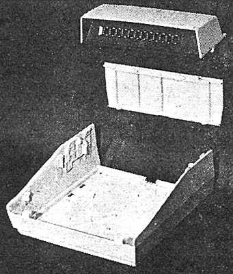
As well as being advanced electronically, the Anita was also advanced in its construction. The following is an extract from the journal "Engineering" for March 1962:
"Intricate Moulding in ABS Plastic
A moulded plastics
casing shown here is described by the makers, GEC (Engineering) Limited, Erith, as being particularly complex. This component forms the casing of the new Anita electronic desk calculator being marketed in the United Kingdom
by Sumlock-Comptometer Limited.
The casing is of fabricated construction comprising 13 moulded items varying in weight from 0.13 to 50 oz. It is made of Cycolac T, an ABS plastic. This is said to have been chosen because of its
strength and good surface finish.
The Moulded Plastics Division of GEC comment that because of the intricate nature of the design, several new techniques were evolved. One of the problems was the variation in thickness
particularly at the points where bosses and fixing brackets were required. This was largely overcome, they add, by casting these bosses and brackets as separate items and then dovetailing and cementing them into position on the
main component afterwards."
Sales brochure for the ANITA Mk 8 (pdf format, courtesy of Matthew Mawson).
Operating Instructions for the ANITA Mk 8 (pdf format).
Review of the ANITA Mk 8, written in late 1961 when the machine was launched.
Roland Huisman at http://technischmuseum.nl has described his restoration of an ANITA Mk 8 to working order at http://technischmuseum.nl/devices/Anita%20MK8/Anita%20MK8.html,
with much very interesting information about the working of this machine. Note that this article is in Dutch but can be translated using https://translate.google.com/.
Roland has
also uploaded a video to the YouTube site of the ANITA Mk8 operating. This is very informative since the machine has the cover open and Roland explains what is happening internally. See the video at https://www.youtube.com/watch?v=6-qvtiqWens.
The ANITA Models Mk VII and Mk 8 were the only electronic desktop calculator for over 2 years, until 1964 when the transistorised Friden 130, IME 84, and Sharp Compet CS10A were introduced. In this time several tens of thousands of ANITAs were sold world-wide.
If you have information about the development of ANITA calculators, or know of somebody who worked there, please get in touch with us.
Grateful thanks to Ken Buckles for the opportunity to acquire this machine.
Reference:
Early Anita Desktop Calculators
Text & photographs copyright © 2002 - 2023 Nigel Tout, except where noted otherwise.